A microcontroller is an integrated circuit with the capacity to be programmed several times, depending on the code recorded in its memory, to execute the different commands that we indicate to it. They are mainly composed of three blocks: the Central Processing Unit (CPU), the memory and the input or output peripherals.
ESP8266 features
This microcontroller manufactured by the company Espressif incorporates, in addition to the three basic modules of a controller, a Wi-Fi module for communication. On the boards on which this chip is placed, antennas are printed in a compact way to be able to use such communication. This makes the ESP8266 versions a small, but very powerful device.
Its CPU is based on a 32-bit processor and its Wi-Fi chip integrates TCP/IP stack management, which makes the ESP8266 a microcontroller with full Wi-Fi connectivity.
The memory of this microcontroller is a Flash memory whose size varies from 1MiB (1MiB = 1.04858 MB) to 8MiB, although ESPs with up to 16MiB of Flash memory can be found in the market. This memory will be used to store both the program that we write and to store locally certain information such as Wi-Fi passwords or some data that we consider private.
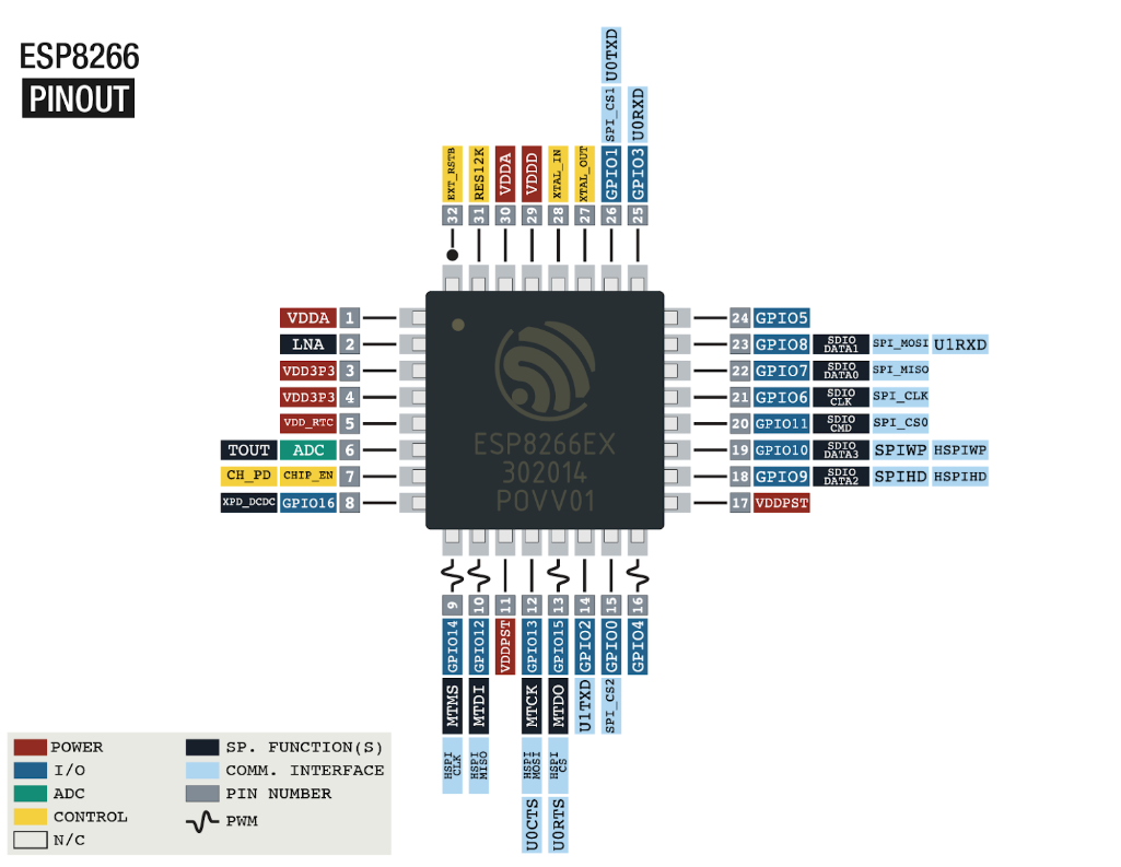
Regarding peripherals, the ESP8266 has 16 GPIO (General Pins Input Output) pins that can be used for, as its name suggests, general purpose. It also has several communication protocols such as UART, SPI, I2C, I2S and the possibility of 10-bit PWM outputs on all its GPIO pins.
A summary of its characteristics could be the following:
- 32-bit RISC CPU, with a clock of 80 MHz (maximum 160MHz).
- 32 KiB RAM instructions, 32 KiB RAM cache
- 80 KiB RAM for user data
- External Flash memory between 1 and 8 MB (maximum 16MiB)
- Wifi 802.11 b/g/n 2.4GHz (supports WPA/WPA2)
- FCC, CE, TELEC, WiFi Alliance and SRRC certified
- 16 pins GPIO
- PWM on all pins (10 bits), UART, SPI, I2C and I2S
- 10-bit analog-to-digital converter (Up to 1V)
- Operating voltage 3.0 to 3.6V
- Average consumption 80mA
- Stand-by consumption mode (1mW) and deep sleep (1uA)
Available versions
There are several models of boards that incorporate this microcontroller. We will see the ones currently available, from the simplest and most compact to the most complete.
ESP-01
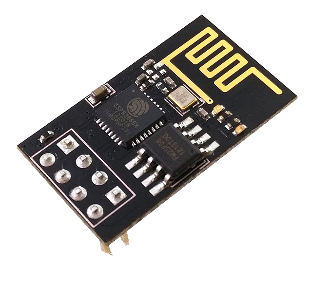
The first version released was the ESP-01, designed to be used as a Wi-Fi interface for Arduino boards. However, its great acceptance in the maker community soon led to the release of the following versions until the ESP-12, the most widespread.
ESP-12
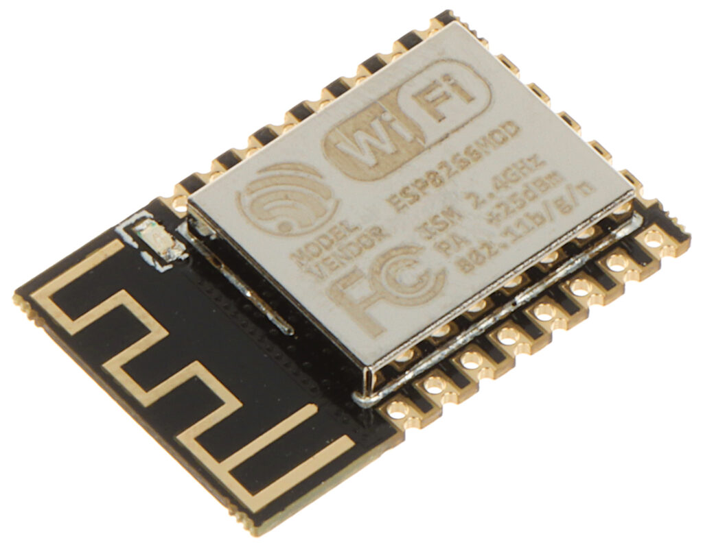
This version has become the flagship of the brand. It allows you to create more complete projects than its previous versions, at a fairly reduced price. It can be programmed to use its Wi-Fi module, to enter a low-power mode (without Wi-Fi) and to “sleep” (Deep-Sleep mode) with minimal current consumption.
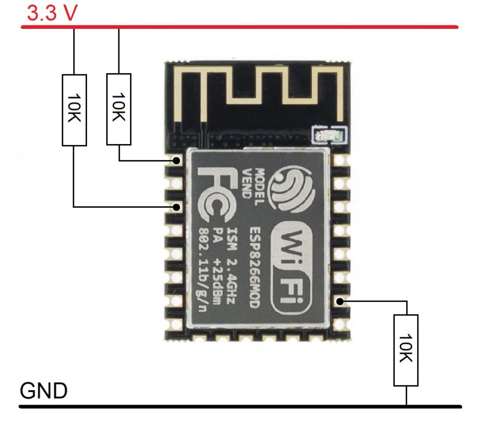
However, to connect it to a breadboard, include it in your projects or directly program it, you will need additional tools. The pins are 2.00mm apart as opposed to the standard 2.54mm found on most components and breadboards. There is a board to adapt to this pin spacing that also has the three minimum resistors needed for its use: 3 resistors of 10Kohm connected as shown in the following image.
To program this version of the ESP, you will need either to create the necessary circuitry for UART communication, plus a USB to TTL converter; or directly a board prepared with a microUSB port through which you can connect to your PC and program this microcontroller.
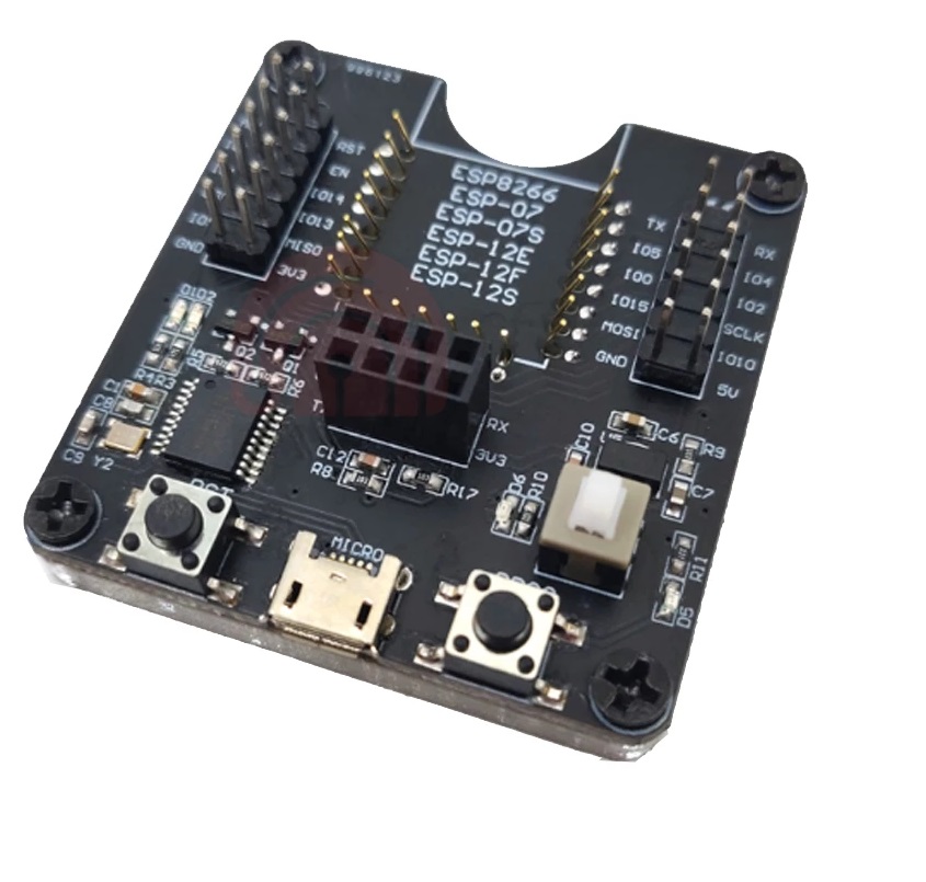
This programming board also has Dupont-style male pins connected directly to each pin of the microcontroller, so you can connect peripherals or other components at the same time as you test the code you have just installed.
WeMos D1 Mini
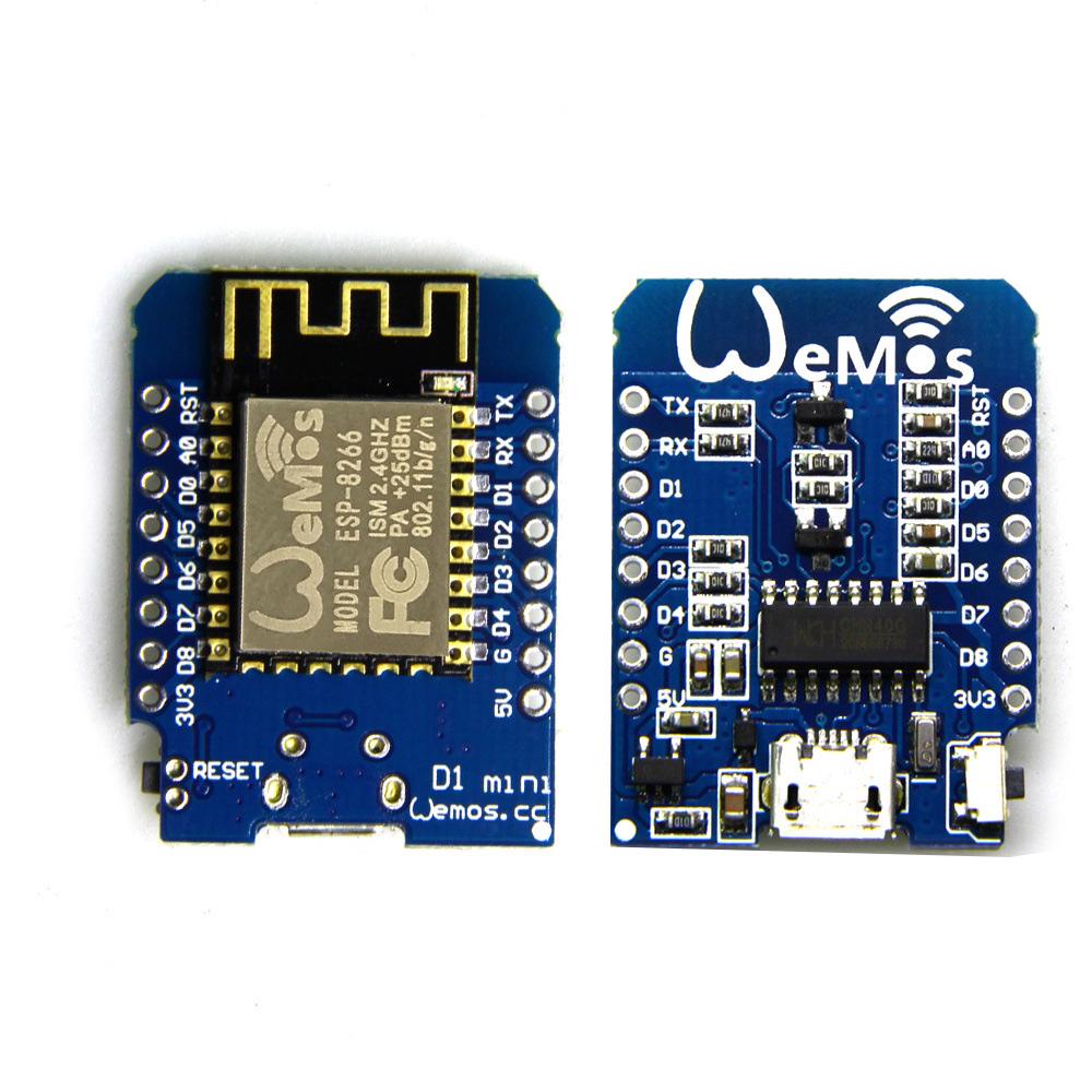
This version of the ESP8266 is based on the ESP-12 model soldered on a board with everything you need to power, program and test your WeMos code.
It has a microUSB port where you can power and load the program, plus the integrated chips needed for TTL conversion, the minimum resistors needed and a small reset button for when the code does not go as expected and you need to restart it.
This version also has access to almost every pin of the microcontroller with a 2.54mm pitch, ideal for use in any prototyping scenario. It usually comes with three different pin pairs: male, female and a mix of female on one side and male on the opposite side, so that for the same pin, you can connect two peripherals.
Node MCU
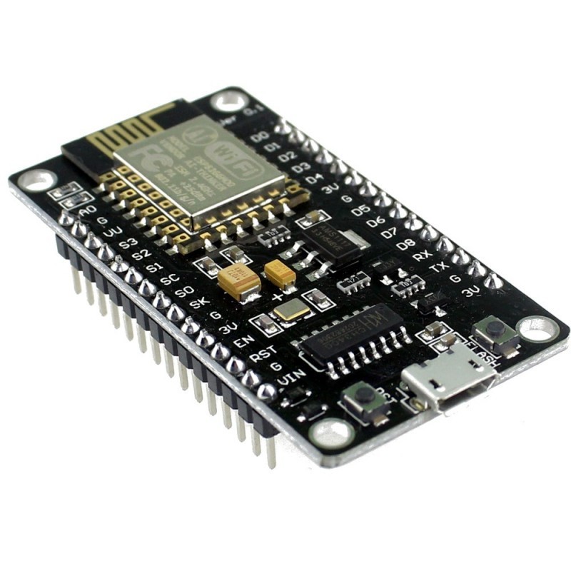
Slightly more complete than the WeMos D1 Mini version is the Node MCU version. Like its smaller version, it has a microUSB port for serial communication with a PC or for powering through a charger or battery. It has access to all pins of the ESP-12, unlike the WeMos, where the pins on the side opposite the antenna were not accessible.
This version would be the most complete version available today using the ESP-12 model as microcontroller.
ESP32
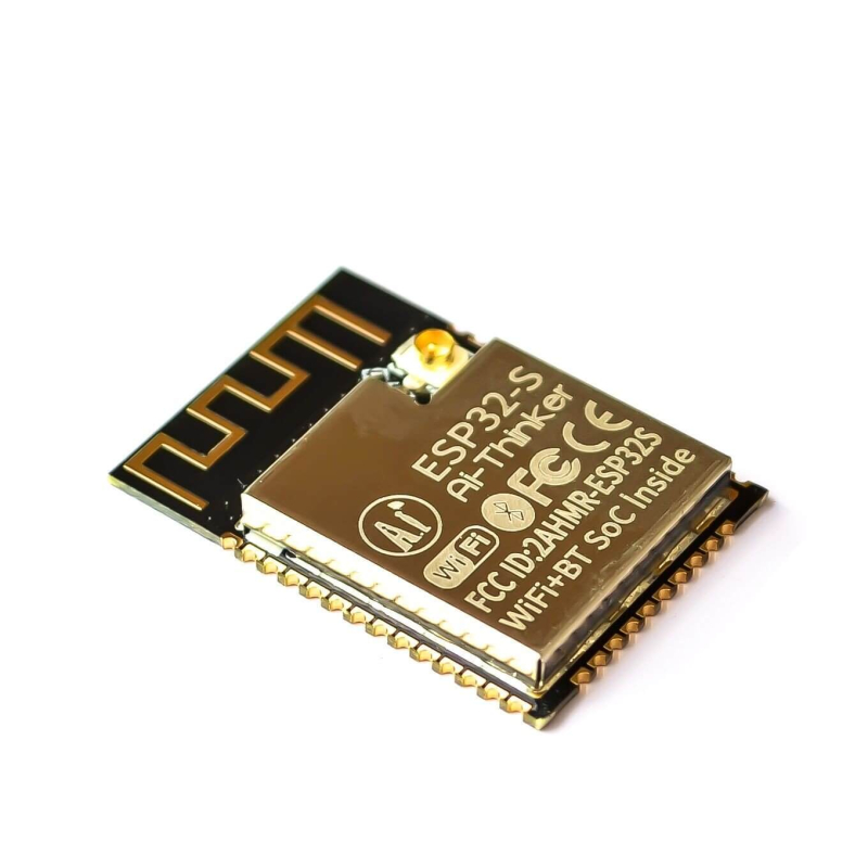
The ESP32 is an upgraded version of the ESP8266 that includes in addition to the Wi-Fi connectivity of the previous model, Bluetooth connectivity, an additional core and a larger number of GPIO pins. In addition, for the ESP32, Wi-Fi connectivity has been improved allowing higher speeds than in its previous version.
Like the ESP-12, this version alone requires external circuitry to operate and to load software.
Its most important features are:
- Xtensa Dual-Core 32-bit LX6 CPU.
- Bluetooth 4.2 and Bluetooth Low Energy (Low power consumption)
- 160MHz clock (Maximum 240MHz)
- Integrated 520 KB of SRAM
- 4MB Flash memory
- Hall effect sensor
- UART, SPI, I2C, I2S, PWM communications on its GPIO and Radio pins
- Contains an ADC with 12-bit resolution
- Incorporates touch sensors and Ethernet MAC interface.
ESP32 DevKitC
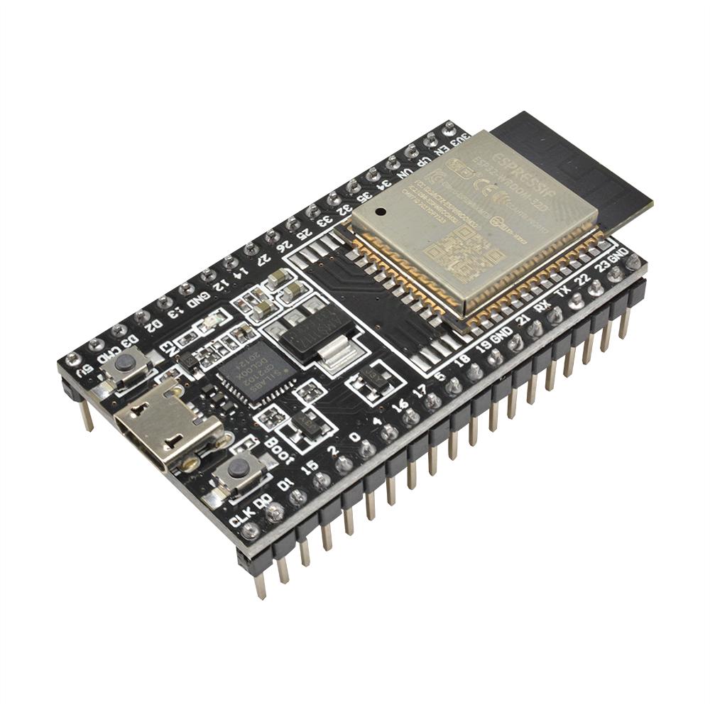
Like the Node MCU, the ESP32 has a more complete version called ESP32 DevKitC.
It incorporates, in addition to the microcontroller, all the necessary components for serial communication, power supply and use in any prototyping environment.
Programming
The programming of all these previous models can be done through the Arduino IDE. To download this programming environment, we will have to look for it in the Microsoft Store apps for Windows OS or download it directly from their website for Linux (https://docs.arduino.cc/software/ide-v1/tutorials/Linux).
Once downloaded and installed, we will open the program and add our ESP8266 or ESP32 based board. To do this click on File > Preferences. A window like the one in the image below will open. We will have to enter the following URL in the field “Additional Board URLS Manager”: http://arduino.esp8266.com/stable/package_esp8266com_index.json
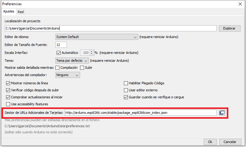
Click on “Ok” and now open the menu Tools > Board: “Arduino/Genuino UNO” > Board manager….
Here, a window will open where we can search for all the boards we want to work with. To add ESP8266 boards, just type “ESP” and the “esp8266 by ESP8266 Community” board will appear.
Once everything is installed, we must choose which board we are going to use. To do this we click again on Tools > Board: and choose our board.
Deep sleep
One of the advantages of the ESP8266 controller is that it can be programmed to enter a very low power mode called Deep Sleep. In this sleep mode the controller will remain without performing any task, but when the time that was programmed for the device to “sleep” passes, it will be as if it had been restarted and will start executing its recorded code from the beginning.
To get the microcontroller into this state, it is as simple as typing the command ESP.deepSleep(time); where time is the time it will remain sleeping, in microseconds (1E-6 Seconds).
For the ESP to exit this state, it is necessary that the GPIO16 pin is connected to the board’s own Reset pin. This pin 16 is the pin programmed to send a high value signal when the time indicated by the ESP.deepSleep() function elapses. When connected to the Reset pin, the microcontroller will reboot and start executing the loaded code again.
It is important to know that, if you want to load a new code to the microcontroller, we must undo this GPIO16-Reset connection, otherwise the Arduino IDE will not be able to find our microcontroller.
Examples
Next, we will look at a series of simple examples to see how this microncontroller works.
Blink
This example can be found in the examples included in the ESP8266 card library.
void setup() {
  pinMode(LED_BUILTIN, OUTPUT);     // Initialize the LED_BUILTIN pin as an output
}

// the loop function runs over and over again forever
void loop() {
  digitalWrite(LED_BUILTIN, LOW);   // Turn the LED on (Note that LOW is the voltage level
  // but actually the LED is on; this is because
  // it is active low on the ESP-01)
  delay(1000);                      // Wait for a second
  digitalWrite(LED_BUILTIN, HIGH);  // Turn the LED off by making the voltage HIGH
  delay(2000);                      // Wait for two seconds (to demonstrate the active low LED)
}
AHT20 sensor reading
To take data from this sensor, we must add the corresponding libraries. To do this, click on Tools > Add Libraries and in the search bar type “AHT20”. We will look for the Adafruit library called “Adafruit AHTX0”.
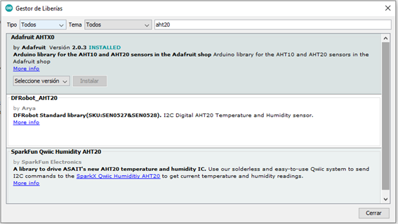
Once this library is installed, the simplest example is the following:
#include <Adafruit_AHTX0.h>

Adafruit_AHTX0 aht;

void setup() {

  Serial.begin(115200);

  Serial.println("Adafruit AHT10/AHT20 demo!");

  if (! aht.begin()) {

    Serial.println("Could not find AHT? Check wiring");

    while (1) delay(10);

  }

  Serial.println("AHT10 or AHT20 found");

}

void loop() {

  sensors_event_t humidity, temp;

  aht.getEvent(&humidity, &temp);// populate temp and humidity objects with fresh data

  Serial.print("Temperature: "); Serial.print(temp.temperature); Serial.println(" degrees C");

  Serial.print("Humidity: "); Serial.print(humidity.relative_humidity); Serial.println("% rH");

  delay(500);

}
Deep Sleep
/*

   ESP8266 basic deep sleep example deep sleep

*/

void setup() {

  Serial.begin(115200);

  // Wait until Serial monitor is available

  while (!Serial) { }

  /*

     Insert your code here for obtaining sensor's values

     and send information to any platform.

  */

  Serial.println(" ");

  Serial.println("Temperatura: 25,5ºC");

  delay(1000);

  Serial.println("Conectando red WiFi...");

  delay(1000);

  Serial.println("Enviando información a ThingSpeak");

  delay(1000);

  Serial.println("Modo ESP8266 deep sleep durante 10 segundos");

  ESP.deepSleep(20e6); // 10e6 es 10.000.000 microsegundos

  Serial.println("Esto nunca se mostrará por el monitor serie");

}

void loop() {

}
Where to buy it?
Based on our purchasing experience, our two main suppliers are Tiendatec and Bricogeek. You can find a wide variety of ESP8266-based micronotrollers on their respective websites or at these links:
References
https://programarfacil.com/esp8266/esp32
https://vasanza.blogspot.com/2021/07/especificaciones-del-modulo-esp32.html
https://www.luisllamas.es/esp8266
https://es.wikipedia.org/wiki/ESP8266
https://programarfacil.com/podcast/esp8266-wifi-coste-arduino
https://programarfacil.com/podcast/como-configurar-esp01-wifi-esp8266
https://programarfacil.com/esp8266/esp8266-deep-sleep-nodemcu-wemos-d1-mini
Good information in one post.